Subsea Fiber Optic Cables: The Invisible Backbone Powering Global Internet Telemetry & Transcontinental Latency
Explore how 99% of all international data travels across 1.4 million kilometers of undersea glass cables. Discover the physics of light propagation, DWDM laser amplifiers, subsea repeaters, cable landing stations, and why physical geography dictates your speed test ping.
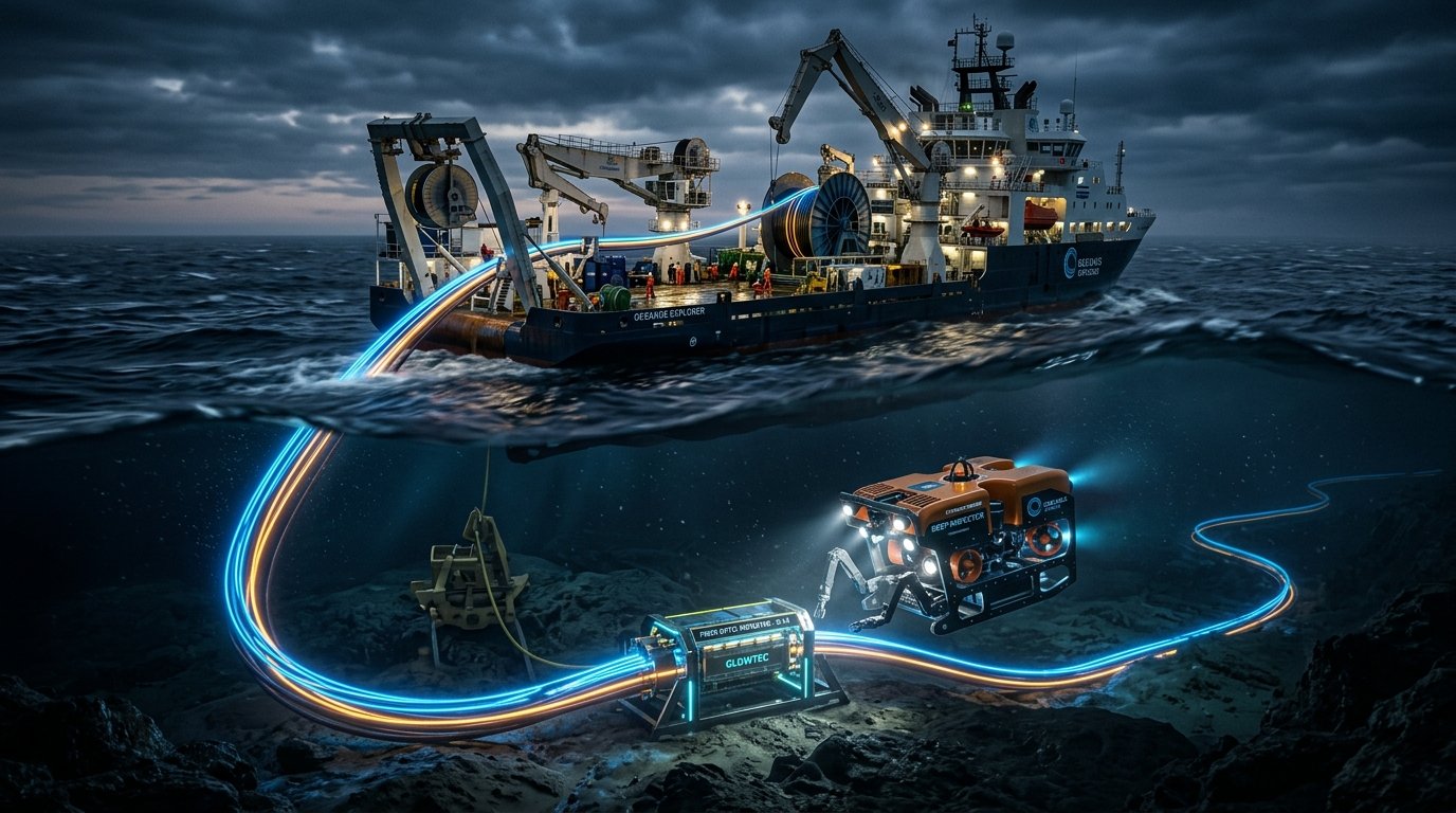
Whenever you initiate an international video conference between London and Singapore, execute an algorithmic trade on Wall Street from Tokyo, or run a global latency benchmark on WRLDU Speed Test, your packets do not float through orbital satellite constellations. Over 99% of all intercontinental internet traffic traverses approximately 1.4 million kilometers of fiber optic cables resting silently on the dark floor of the world's oceans.
Subsea telecommunications cables are the unsung engineering marvel of modern human civilization. Despite being no thicker than a garden hose in the deep abyss, a modern transoceanic cable system carries hundreds of terabits of bidirectional data per second across thousands of nautical miles. In this comprehensive technical breakdown, we examine the physics of subsea fiber optics, investigate the hardware powering transoceanic repeaters, explore the geopolitical choke points of global connectivity, and explain why physical light propagation dictates the absolute speed limit of your internet connection.
1. The Anatomy of an Undersea Fiber Optic Cable
To withstand extreme benthic water pressure (exceeding 8,000 PSI at depths of 5,000 meters), shark bites, corrosive saltwater, and shifting tectonic plates, an undersea cable is built with multi-layered protective shielding. Contrary to popular belief, the actual optical fibers comprise only a microscopic fraction of the cable's physical volume.
| Layer Component | Material Composition | Primary Engineering Purpose |
|---|---|---|
| 1. Optical Fibers | Ultra-pure fused silica glass (SiO₂) | Carries pulsed laser light signals across core and cladding using total internal reflection. |
| 2. Thixotropic Water-Blocking Gel | Hydrophobic petroleum/silicone gel | Prevents longitudinal water migration in the event of an outer sheath puncture or fracture. |
| 3. Stainless Steel Tube | Hermetically sealed laser-welded steel | Houses the loose fiber tubes and absorbs massive hydrostatic crushing pressure. |
| 4. High-Tensile Steel Strands | Helically wound galvanized steel wires | Provides tensile strength during deployment and recovery from depths exceeding 6,000 meters. |
| 5. Copper / Aluminum Tube | Conductive barrier tube | Transmits up to 10,000 Volts DC to power inline optical optical repeaters spaced across oceans. |
| 6. Polycarbonate Insulator | High-dielectric polymer | Isolates the high-voltage electrical conductor from the grounded sea water. |
| 7. Double Steel Armor (Shallow Water Only) | Heavy braided galvanized steel wire | Shields cable from commercial fishing trawler nets, scallop dredges, and ship anchors. |
| 8. Polyethylene Outer Jacket | High-density polyethylene (HDPE) | Forms the outermost waterproof and abrasion-resistant external barrier. |
In deep water (beyond 1,500 meters), the cable is remarkably lightweight and unarmored—measuring approximately 17 millimeters (0.7 inches) in diameter—because the deep ocean floor is peaceful and devoid of human disturbance. However, as the cable approaches shallow coastal shelves within 500 meters of the coastline, heavy interlocking layers of galvanized steel armor are added, increasing the cable diameter to over 50 millimeters and multiplying its weight tenfold to guard against ship anchors.
2. Optical Physics: Why Speed Test Latency Has a Hard Physical Limit
Many internet users wonder why their ping to an overseas server (such as New York to Frankfurt or Los Angeles to Sydney) cannot be reduced to 0 milliseconds. The answer lies in the fundamental physics of optical refraction and the speed of light.
The Speed of Light in Silica Glass Formula
In a vacuum, light travels at c = 299,792.458 km/s. However, inside the core of a single-mode silica optical fiber, light is slowed down by the material's refractive index (n), which is typically n ≈ 1.4682 at the standard 1550 nm telecommunications wavelength:
v = c / n = 299,792 km/s / 1.4682 ≈ 204,190 km/s
This means that light travels through fiber optic glass at roughly 204 kilometers per millisecond, or approximately 4.89 microseconds per kilometer of one-way travel.
Calculating Theoretical Minimum Round-Trip Time (RTT)
Consider the transatlantic route between New York and London, spanning an undersea cable length of roughly 6,600 kilometers:
- One-Way Fiber Propagation Delay: 6,600 km × 4.89 μs/km ≈ 32.3 ms
- Round-Trip Time (RTT) in Pure Glass: 32.3 ms × 2 ≈ 64.6 ms
- Terrestrial Backhaul, Routing & Switch Handoffs: Adding landing station backhauls, optical transponders, and BGP routing adds roughly 8–14 ms.
- Real-World Benchmark: The fastest commercial transatlantic cables (such as Amitié and Dunant) achieve real-world ping times of 68 ms to 74 ms RTT.
No software optimization, ISP upgrade, or gaming VPN can ever surpass this physical threshold. You can verify your own regional and intercontinental routing delays right now using the WRLDU Real-Time Ping & Latency Monitor.
3. Subsea Repeaters & Dense Wavelength Division Multiplexing (DWDM)
As photons travel through fused silica glass, they suffer from optical attenuation (energy loss) caused by Rayleigh scattering and absorption. In modern Corning Vascade fibers, attenuation averages approximately 0.15 dB per kilometer at 1550 nm. After traversing 80 to 100 kilometers, the signal becomes too faint for receivers to detect without amplification.
How Erbium-Doped Fiber Amplifiers (EDFA) Work Underwater
To overcome signal degradation, subsea cables integrate torpedo-shaped titanium repeater housings every 60 to 100 kilometers along the ocean floor. Inside each repeater:
- The optical signal enters a coil of silica fiber doped with trivalent ions of the rare-earth element Erbium (Er³⁺).
- Inline 980 nm or 1480 nm semiconductor pump lasers continuously excite the erbium ions into higher energy states.
- When incoming data photons collide with the excited erbium ions, stimulated emission occurs, producing identical photons with matching wavelength and phase.
- The light signal is amplified purely optically—without converting light to electricity and back—achieving distortion-free signal boosting with zero latency penalty!
Dense Wavelength Division Multiplexing (DWDM)
A single pair of optical fibers does not carry just one laser stream. Using DWDM, telecommunications engineers multiplex dozens of distinct wavelengths (colors) of light down a single strand of hair-thin glass. By employing 64-QAM modulation and coherent optical transponders operating at 800 Gbps per wavelength across 40 channels, a single fiber pair can transport over 30 Terabits per second (Tbps). Modern transoceanic cables with 16 to 24 fiber pairs achieve staggering total system capacities exceeding 500 Tbps!
4. Cable Landing Stations (CLS) to Terrestrial Backbones
When an undersea cable reaches a continent, it enters a protective subterranean conduit drilled horizontally under the beach (using Horizontal Directional Drilling, or HDD) to emerge safely inland at a Cable Landing Station (CLS).
The Cable Landing Station performs three critical missions:
- Power Feed Equipment (PFE): High-voltage DC power generators inject constant electric current (up to 10 kV at 1.5 Amps) into the copper conductor to power all undersea repeaters across the ocean.
- Submarine Line Terminal Equipment (SLTE): Massive coherent optical transponders receive, demultiplex, and error-correct the incoming laser signals using Forward Error Correction (FEC).
- Interconnection to Terrestrial Backbones: The high-capacity optical stream is handed off to terrestrial dark fiber routes, connecting directly to major carrier-neutral data centers and Internet Exchange Points (IXPs) in metropolitan hubs like Ashburn, Frankfurt, Singapore, and Tokyo.
To inspect your current network path, upstream autonomous system (ASN), and ISP peering gateways, run the WRLDU IP & ASN Intelligence Tool.
5. Global Chokepoints, Anchor Snags, and Cable Repair Fleets
Despite their sophisticated technology, undersea cables remain vulnerable to physical hazards. On average, between 100 and 150 subsea cable faults occur worldwide every year.
Primary Causes of Subsea Cable Outages
- Commercial Fishing & Ship Anchors (70%): Accidental snagging by heavy deep-sea bottom trawlers and dragging merchant vessel anchors is the dominant cause of cable cuts.
- Geological & Seismic Activity (15%): Underwater earthquakes, underwater landslides (turbidity currents), and tsunamis (such as the 2006 Hengchun earthquake in Taiwan, which snapped eight major undersea cables simultaneously).
- Maritime Geopolitical Chokepoints (10%): Areas like the Red Sea (Bab-el-Mandeb strait), the Strait of Malacca, and the Suez Canal concentrate dozens of intercontinental cables into narrow, shallow waterways where ship congestion creates severe vulnerability.
- Component Failures (5%): Rare high-voltage electrical shunts or laser diode degradation inside submarine repeaters.
How a Subsea Cable Is Repaired at Sea
When an undersea cable is severed in deep water, the process of restoring connectivity is a complex maritime operation:
- Fault Location: Engineers at the landing stations transmit high-frequency electrical and optical pulses (Optical Time-Domain Reflectometry, or OTDR) down the fiber. By measuring the exact microsecond timestamp of the reflection, they pinpoint the break location within a few meters.
- Mobilizing the Cable Ship: A specialized cable ship (like those operated by SubCom, Alcatel Submarine Networks, or Orange Marine) sails to the coordinate.
- Grapnel Retrieval or ROV Intervention: In deep water, a specialized cutting and holding grapnel is lowered to hook the cable. At moderate depths, an unmanned Remotely Operated Vehicle (ROV) equipped with robotic arms, sonar, and high-definition cameras cuts and secures the cable ends.
- Cleanroom Fusion Splicing: The cable ends are hoisted onto the ship's cleanroom deck. Highly trained optical technicians strip the protective layers and use electric arc fusion splicers to rejoin each microscopic glass fiber strand by strand.
- Re-Deployment: A waterproof joint housing is sealed over the splice, and the repaired cable is gently lowered back onto the seabed.
6. How to Benchmark Your Intercontinental Network Path
Because major tech platforms (such as Google, Cloudflare, Microsoft, and Meta) maintain multiple redundant subsea cable routes, an undersea cut usually triggers automated BGP rerouting within seconds. However, this rerouting forces traffic onto longer terrestrial or oceanic paths, causing latency spikes and jitter.
| Diagnostic Objective | Recommended WRLDU Diagnostic Utility | Optimal Target Metric |
|---|---|---|
| Direct Line Throughput | WRLDU Network Speed Test | Full line saturation across parallel HTTP/2 download sockets. |
| Oceanic Latency Jitter | Real-Time Ping & Jitter Monitor | RFC 3550 Jitter under 2.5 ms to regional nodes. |
| Bufferbloat & Loaded Latency | Internet Quality Diagnostics | Quality Score Grade A+ or A (Loaded ping increase < 15 ms). |
| ASN & Geolocation Inspection | IP & ASN Intelligence Lookup | Direct Tier-1 ISP peering without transit degradation. |
Frequently Asked Questions (FAQ)
Do sharks bite undersea fiber optic cables?
While early experimental coaxial cables in the 1980s experienced occasional shark bites (likely attracted by electromagnetic fields induced by early power systems), modern subsea cables utilize advanced multi-layered copper conductors, high-dielectric insulators, and heavy double steel armoring. There has not been a single documented cable failure caused by shark bites in over two decades.
Why don't we use satellites for all international internet traffic?
Low-Earth Orbit (LEO) satellite megaconstellations like Starlink are fantastic for remote rural users, maritime vessels, and aviation. However, a single modern subsea fiber cable delivers over 250 to 500 Terabits per second of dedicated bandwidth with zero weather interference (no rain fade) and consistent microsecond latency. Satellite radio frequency bands simply lack the aggregate spectral capacity to handle global petabyte-scale intercontinental data flows.
Can a severed subsea cable shut down the internet in an entire country?
For nations with diverse telecommunications infrastructure (like the USA, Germany, Japan, or Singapore), traffic is instantly rerouted across dozens of alternative cables within milliseconds. However, developing island nations or landlocked countries relying on only one or two international landing stations can experience widespread outages or severe bandwidth rationing until repair ships arrive.
To audit your current broadband reliability and ensure your home connection is operating at full physical capacity, run a comprehensive diagnostic today on WRLDU Speed Test.